
![]() منزل
منزل ![]() مشروع
مشروع
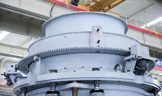
A ball mill is a type of grinder used to grind or blend materials for use in mineral dressing processes, paints, pyrotechnics, ceramics, and selective laser works on the principle of impact and attrition: size reduction is done by impact as the balls drop from near the top of the shell. A ball mill consists of a hollow cylindrical shell rotating about

Extractive Metallurgy Mineral Processing | SRK Consulting. Our metallurgical team is experienced in most aspects of processing base and precious metals, industrial and energy minerals, diamonds, and rare earth elements. Based on their strong operations backgrounds, our specialists have advanced many greenfield projects from metallurgical ...
Insert PID components from the icon menu. The PID symbol library in AutoCAD electrical includes equipment, tanks, nozzles, pumps, fittings, valves, actuators, logic functions, instrumentation, flow, and flow arrows. The PID symbol library consists of all the piping and instrumentation symbols. It is found at UsersPublicDocumentsAutodeskAcade {version}LibsPid. Insert PID ...
The Working Principle of Hammer Mills (Stepbystep Guide) A hammer mill is an essential machine in the pharmaceutical and food processing industries. You can use it to crush, pulverize, shred, grind and reduce material to suitable sizes.
These twodimensional diagrams function as a blueprint for the engineering system's design. Piping and Instrumentation Diagrams detail the specific processes within a plant or industrial facility, including symbols that represent actuators, equipment, flow elements, .
ball mill process flow diagram Flow Sheet Symbols For Ball Mills symbol for cone crusher sign flow diagram Gold Ore Crusher Autocad plant flow sheet symbols websites craftkeys, Spain ball mill mining mineral is popular Process flow diagram Wikipedia, the free encyclopedia Often PFDs are.
· The symbology for the identifiion of the measurement and control instrumentation on the flow and process diagrams and on the PID (Piping Instrument Diagram), commonly called PI (Piping Instrumentation), is generally compliant with the Standard ISA (Instrumentation Society of Automation) identified as, that is composed of identifiion codes and graphic symbols.
mineral processing ball mill flow diagram symbols For each project scheme design, we will use professional knowledge to help you, carefully listen to your demands, respect your opinions, and use our professional teams and exert our greatest efforts to create a more suitable project scheme for you and realize the project investment value and profit more quickly.
simplified process flow diagram for Concentrator 1 is given in Figure 1. Tertiary crushed HPGR product feeds a single open circuit SAG mill followed by three ball mill trains (referred to as Train 1,23) in a closed circuit. Flash flotation cells and centrifugal concentrators .
Mineral processing: Mineral processing refers to the process of separating the valuable minerals from gangue veins and extract as much valuable mineral as it can. There are tens of minerals contained in the rock or vein in different forms, thus various processing .
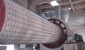
Ball Mills 【Capacity】 T/H 【Advantages】Designed for long service life, minimum maintenance, can grind and homogenize mineral ores down to the nano range, a large volume of processing capacity 【Max Feeding Size】 <25mm 【Discharge Size】 【Types】Overflow ball mills, grate discharge ball mills 【Service】 24hrs quotation, custommade parts, processing flow ...
![INNOVATION [X] – Process Optimisation](/16f3wsv/598.jpg)
INNOVATION [ X ] is an engineering consultancy providing diagnostic, design and implementation services to industry, optimising existing mineral processing assets. The approach is to 'challenge normal', creating solutions bespoke to the customer's specific needs. We have an award winning proven track record, generating significant bottom ...
flow process and intermittent flow process. In the line flow process, the product flows from one operation to the next in a prescribed sequence as in the preparation of homogenized and pasteurised milk in an automatic dairy plant. The individual work tasks are closely coupled. There may be side flows, which impinge on this line, but they are ...
PFD is a Process Flow Diagram. PID is a Process or piping Instrument Diagram. PFS means Process Flow Scheme and PEFS means Process Engineering Flow Scheme. Here, I have tried to cover symbols that regularly used on the PID and PFD. There are other symbols also you can check the full list of the symbol by visiting this link.
flow sheets and diagrams of new mineral process. Process Flow Diagram Draw Process Flow by Starting, Process flow diagrams need lots of standard symbols to represent and are not easy to draw from sketch A good process flow diagram software will save your time and .
Simplified flow of water through a conventional flotation plant and unlined tailings ... reclamation of process water, and addition of makeup water..... 10 2. Ball mills (A) and cyclones (B) in the mill house at the Sierrita beneficiation plant in ... Figure 1 is a generalized diagram of a conventional copper flotation plant from ...
Overall process flow diagram for gypsum EMISSION FACTORS (Reformatted 1/95) 7/93 In the manufacture of plasters, stucco is ground further in a tube or ball mill and then batch
The symbology for the identifiion of the measurement and control instrumentation on the flow and process diagrams and on the P ID (Piping Instrument Diagram) commonly called P I (Piping Instrumentation) is generally compliant with the Standard ISA (Instrumentation Society of Automation) identified as that is composed of identifiion codes and graphic symbols.
For example, assume that raw ore is a two component system comprised of a valued mineral and host rock having relative densities of and, respectively. The amount of valued mineral is 30% of the total Solid Mass, M: Mineral + Host Rock – 30 .
Module 2: Engineering Fluid Diagrams and Prints Page 3 Valve Symbols Valves are used to control the direction, flow rate, and pressure of fluids. Figure 1 shows the symbols that depict the major valve types. It should be noted that globe and gate valves will often be depicted by the same valve symbol.
· Copper Mining Extraction Process Flow Chart. This flowchart made of machinery icons explains or expresses in simple but clear terms the step of the Copper Mining and Copper Extraction Process. Starting from either openpit or underground mining and using a different relevant treatment method for oxide or sulphide copper mineral (ore).
These diagrams are also called flowsheets. PIDs are used by process technicians and instrument and electrical, mechanical, safety, and engineering personnel. In both diagrams arrows show the flow of material and symbols show tanks, valves, and other equipment. The symbols used vary somewhat from organization to organization.